
NPN vs PNP Sensor: How to Identify the Output Type
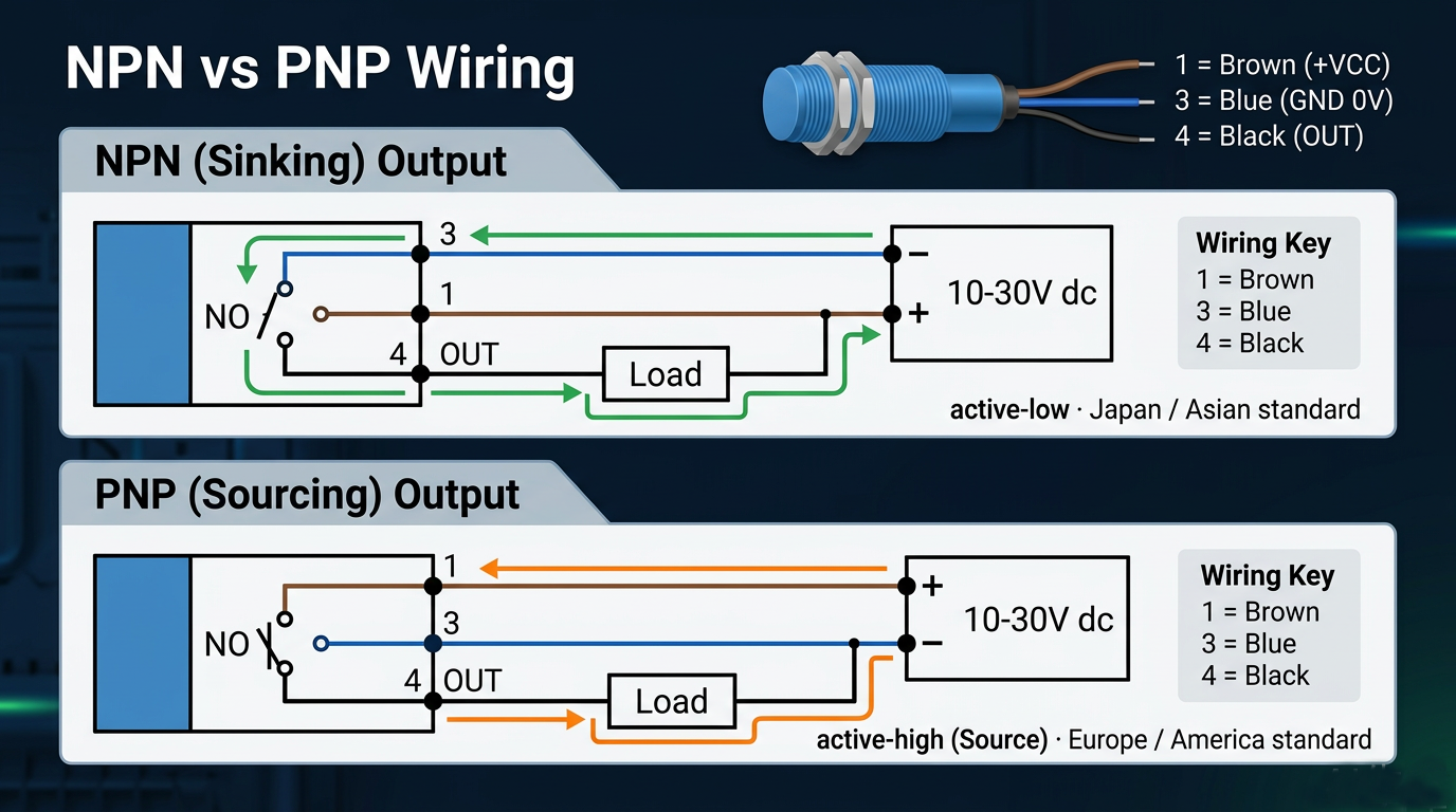
QUICK ANSWER
An NPN output pulls the black signal wire down to 0 V when the sensor triggers - it sinks current. A PNP output drives the black wire up to +V - it sources current. Both are three-wire DC sensors that look identical from the outside.
The letter in the model code is the fastest identifier: ALJ12A3-4-Z/N1 is NPN NO while ALJ12A3-4-Z/P1 is PNP NO from the same M12 housing. The final digit selects the contact state - 1 = NO, 2 = NC, 3 = NO+NC.
A replacement sensor arrives, and the machine stops counting
It is 10:30 on a packaging line. A proximity sensor failed overnight, the spare from the drawer fits the same M12 thread and the same 2 m cable, and the electrician wires it brown to +V, blue to 0 V, black to the input. The line restarts - and the PLC input never changes state again. Nothing is broken; the spare is simply the opposite polarity type.
This is the most common ordering mistake with DC proximity switches, and catalogs make it easy: both types are listed as three-wire DC sensors with the same detection distances, the same IP67 housings and the same cable. The only difference is one letter in the middle of the part number.
Two sensors with the same thread, the same cable and the same range - one runs the line, the other dead-stops it. The difference was one letter in the part number.
What the wrong output type actually costs
An NPN sensor on an input that expects a PNP signal leaves the input floating or permanently latched, so the controller either ignores every target or sees one that never goes away. The line keeps running mechanically while the logic behind it is blind - which is usually discovered as missed counts, skipped rejects or a ram that cycles at the wrong moment.
Here is the part that misleads buyers: modern three-wire DC families carry reverse-connection protection, surge absorption and load short-circuit protection as standard. That protection prevents damaged sensors and burnt inputs from miswiring - it does nothing to make a PNP sensor trigger an input designed for NPN logic. Protection is not compatibility.
So the fix is not better wiring discipline. It is identifying the output type before the sensor reaches the panel - and that takes three checks.
Check 1: Read the model code first
In the catalog's model explanation, the output-form position is explicit: N = three-wire DC NPN, P = three-wire DC PNP, L = two-wire DC, and the A/J family covers two-wire AC. Read the code on the sensor body before reading anything else.
The families on this site spell it out: ALJ12-4 variants run ALJ12A3-4-Z/N1 to /N3 for NPN NO, NC and NO+NC, and ALJ12A3-4-Z/P1 to /P3 for the PNP equivalents. The square-body ASN04 follows the same pattern with ASN-04N1 to N3 and ASN-04P1 to P3. Same housing, same 4 mm or 5 mm range - only the output logic changes.
Check 2: Confirm the wiring convention
Three-wire DC sensors in the catalog's wiring diagrams follow the standard convention: brown to +V, blue to 0 V, black as the switched signal. If the sensor only has two wires, it belongs to the two-wire DC (D type) or two-wire AC (A/J type) families - a completely different connection logic with no separate signal wire, so the NPN/PNP question does not apply.
The AC two-wire variants (ALJ12A3-4-J/A1 and /A2, AC 110-220 V) exist precisely for lines that never had a DC supply near the sensing point. Knowing which family you are holding prevents half an hour of wiring against the wrong diagram.
Check 3: Meter the signal wire under load
With the sensor powered and a load connected, trigger it with a steel target: an NPN output drops the black wire to near 0 V when active, while a PNP output raises it to near the supply voltage. Twenty seconds with a multimeter settles what a rubbed-off label cannot. The contact state adds one more reading: an NO contact closes on trigger, an NC contact opens, and the NO+NC variants give you both from one sensor.
Electrical ratings to keep in mind while testing: the DC families run on 12-24 V nominal (6-36 V absolute), switch up to 200 mA, and respond at 0.8 kHz on the M12 body or 1 kHz on the square ASN04 - far beyond any counting speed a packaging line asks of a proximity switch.
Matching the sensor to your control system
The choice ladder is short. NPN sensors switch the load to 0 V, so they pair with inputs that feed +V through the input terminal; PNP sensors switch to +V and pair with inputs that reference 0 V. Which one is correct is not a preference - it is whatever your PLC input card manual calls a sinking or sourcing input, so confirm that one line before ordering. Need only two conductors to the sensor? Use the two-wire DC D types. Working on an AC 110-220 V line with no DC supply? The J/A two-wire AC family connects directly.
One boundary to respect: this guide covers the catalog's DC three-wire, two-wire and AC switching families. NAMUR two-wire current-controlled types and analog-output sensors follow different interface rules and are covered in their own guides.
Before you order, send us the PLC input card type, the supply voltage and the target material - we will confirm the exact part number, including the NO/NC/NO+NC variant your logic expects. Message us on WhatsApp at +86 186 5776 0640 or email joan@zm-ele.com, and we will reply with the matching ALJ12 or ASN04 variant.
Have Questions?
Our technical team is ready to help you with sensor selection, application support, and custom solutions.
Contact UsRelated Articles

Sensor Selection Guide: How to Find the Best Fit for Your Application
Target material, mounting style, detection distance and environment decide which sensor survives on your line. A four-step walkthrough from spec sheet to part number.
Read More
Capacitive Sensor Application Guide: What Materials and Distances It Covers
Capacitive sensors detect conductors and dielectric bodies alike - plastic, glass, granules, liquids. Where they beat inductive sensors, and the distance ranges you can expect from each family.
Read More
Which Devices Use Analog-Output Sensors, and How Do You Interface with Them?
4-20 mA current loops, 0-5 V and 0-10 V voltage outputs each have a load rule and a wiring habit. Where proportional displacement sensing earns its keep, and how to connect it without noise.
Read More